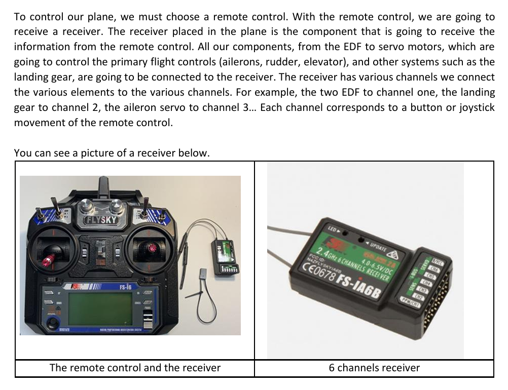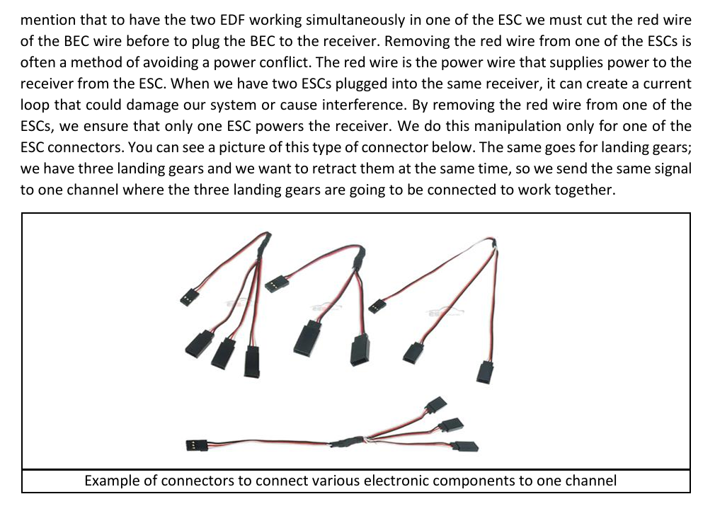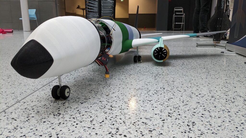
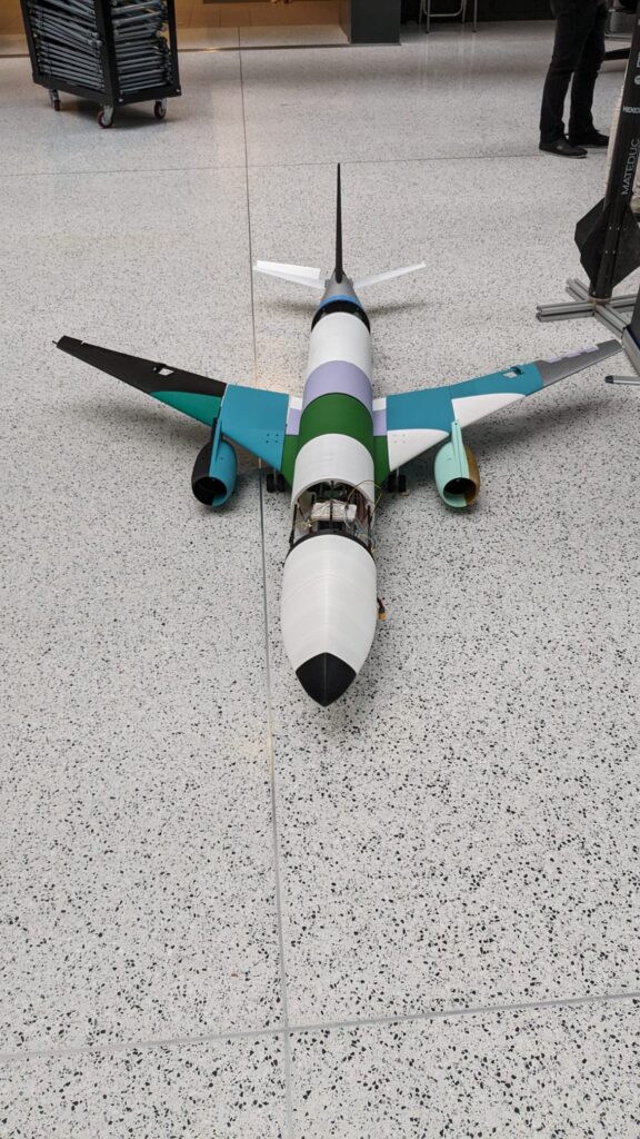
As part of my academic journey, I had the incredible opportunity to lead a groundbreaking aeromodelling project with the association LéoFly. Our ambitious goal? To construct a remote-controlled Airbus A321XLR that not only flies but also embodies efficiency, durability, and innovation. The project marked a turning point for LéoFly, demonstrating that aeromodelling could thrive within our association. Here’s a look at how we made it happen.
Why the Airbus A321XLR?
We chose the Airbus A321XLR for its significance as one of Airbus’ latest and most efficient aircraft models. Inspired by its long-range capabilities, we scaled it down to a 1/21 model and aimed to achieve over 15 minutes of flight time.
Key Objectives and Achievements
- Build a structurally and electronically complete aircraft capable of safe takeoff, flight, and landing.
- Ensure modularity for easy repair and part replacement.
- Maintain a weight below 4 kg and achieve at least 10 minutes of flight time.
- Stay within a budget of €1,000.
Innovative Design and Materials
- 3D Printing and Carbon Tubes: The aircraft structure combined lightweight 3D-printed parts with carbon tubes for strength and modularity.
- Custom Hose Clamps: We designed custom clamps to assemble and secure the carbon tubes without adding unnecessary weight.
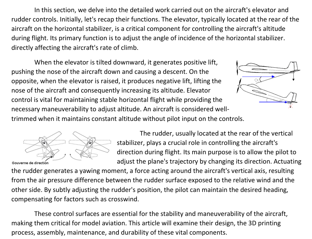
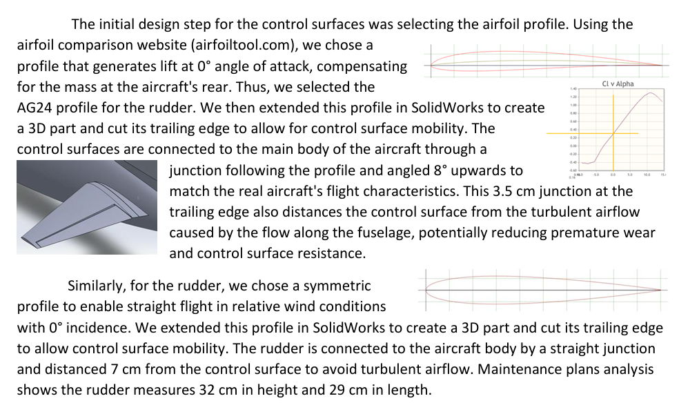
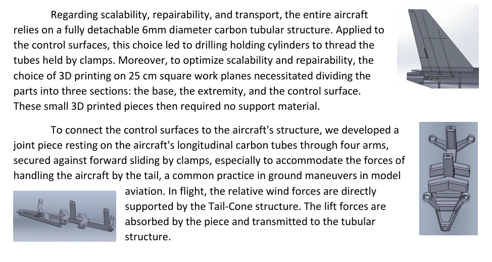
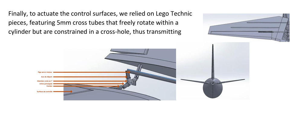
- Tail and Control Surfaces: The rudder and elevators were meticulously designed to ensure stable flight and easy maintenance.
The airplane structure will consist of 3 main elements:
- Carbon tubes making the structure of the plane (Bones)
- 3D printed parts (Binder) to connect the tubes, the two form the
skeleton of the plane. (”Cartilages” connecting the bones) - 3D printed outer surfaces connected to tubes but not taking any effort
(Skin membrane)
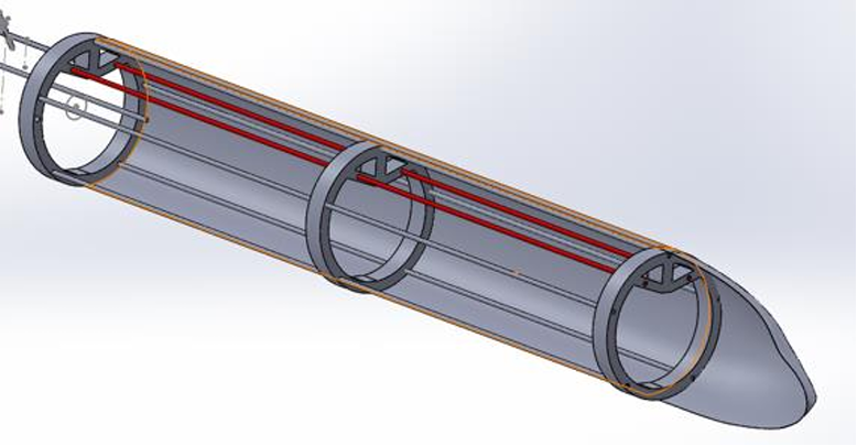
The benefits of using a carbon structure are:
- All aircraft parts are removable and easily replaceable in case of a break. Unlike a fully 3D
printed plane (which would require glue to assemble the sections, we could not fix the sections with metal screw) - The fact of having removable parts also allows to easily and quickly test elements (new wing profile/ Add flaps/ Change the material of the print…)
- As we increase the size of the model, a structure becomes more and more mandatory, so this project will be the basis for a larger aircraft because we will have already developed skills on the structure.
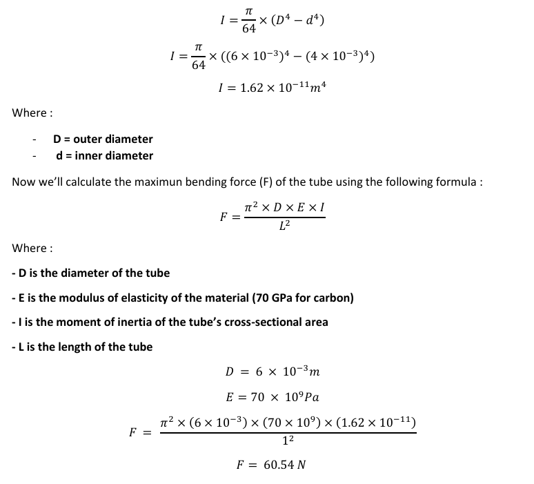
We decided to choose 6 mm carbon tubes as it offered a good balance between bending strength (as
calculated in the following section), cost, and weight. After some modelisation we have established
that we would need about 21 meters of carbone tubes.
Structure and Material Calculations
Undoubtedly, the most important choice in the entire project is that of the main support structure its
constraints are as follows, in order of importance :
- Resistance
- Very little bending
- Lightweight
- Easy to use and machine
With these constraints, we quickly turned to carbon tubes which have excellent bending properties.
So, all that’s left is to theoretically calculate the diameter we’ll need to use :
Materials
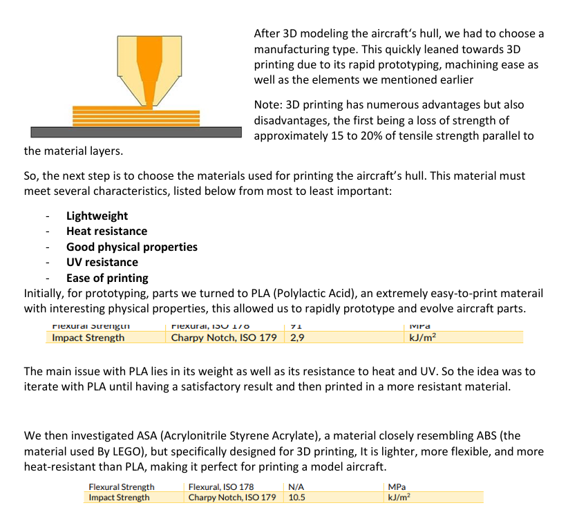

Finally, after multiple research, we discovered a derivative of the materials used, lightweight and heat-resistant, named ASA LIGHT WEIGHT and with that, our choice was made.
Fuselage
Nose
The objective for the nose is to make a structure that can solidly fit the outer surface, while directing the stresses towards the carbon tubes, the nose being the part that will split the air, so it will be subjected to a lot of external forces.
However, having a constraint of weight and printing limit, it will be printed in 2 parts: the tip of the nose will therefore be solid to facilitate the ability to split the air without worrying about the internal structure, in fact being limited by the spacing in width and height of the tip of the nose, make this piece solid instead of creating a structure that would be too thin that would split during a too sudden acceleration or a too much shock.
A simple volume circle is added to integrate the tubes. The result is a simple « start-end » constraint applied, using glues to « patch » or make connections is not welcome.
When we talk about the « start-end » constraint, we mean when we restrict the 6 degrees of freedom at the beginning and end of the same part. Here, the main forces applied to the tip of the nose will only be directed towards the rear of the aircraft. This means that there is no need to apply glue to it.
A second idea to ensure this constraint will be to add the idea of the hose clamp discussed in this second part, on the other hand without using glue to assemble the male and female part of the nose in order to integrate these hose clamps would make this part just as fragile, so we kept the first one
as an idea in application.
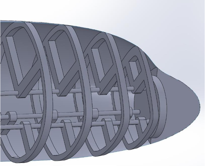
Several « hoops » were positioned at intervals of 4 cm to the tip of the nose and a narrower interval of 2 cm between the last 2 hoops, the shape of the nose to represent the cockpit generating a steep slope of the outer surface bringing the poles closer together and a solution to guarantee solidity despite the change of shape without changing the orientation of the poles and their management for the internal surface.
Now that the problem of fitting the outer surface has been solved, it is now necessary to model the internal structure so that the main stresses are concentrated only on the carbon tubes.
In the first sketch, the idea was to reproduce the idea of the rings discussed in the second part and to adapt it to the nose. On the other hand, the weight limitation does not allow us to do so and it would greatly limit the integration of the nose landing gear. In addition, there is a second constraint: the maximum height of the print, so this part of the nose will be divided into 2 parts.
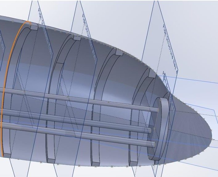
The idea is to connect each of these hoops to the carbon tubes with hook bridges directly.
This approach makes it possible to limit the use of material while adopting a solid and free structure allowing the integration of the landing gear. For a first iteration, the landing gear will not be retractable, but with this in mind, this modeling allows it.
Other constraints are added to printing: impossibility to print these hanging bridges in a vacuum, on the other hand, we will use the bridge technique to compensate for this and we will add chamfers on the lower edges of the hoops so that printing can be possible.
Integration of the landing gear has the same objectives as the structure: To concentrate the forces on the carbon tubes and allow its retraction. This last objective, as discussed, will be implemented in a second iteration, so the opening is made only to allow the landing gear part to pass through.
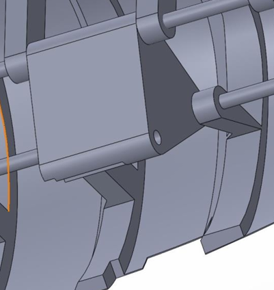
In order to guarantee the removable nature of the different parts of the aircraft but also their solidity, it was necessary to find a way to assemble the parts together by easily accessible and robust elements.
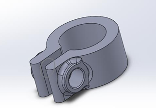
Our first idea was to use metal fasteners, however, in view of their estimated number, around 50, the weight generated by them could not satisfy the specifications in terms of the total weight of the device. This constraint led us to the creation of our own fully 3D printed hose clamps, the only metal parts consisting of screws and nuts allowing the fixing of the carbon tubes and rings that form the skeleton of our aircraft.
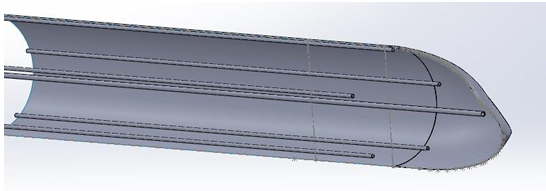
Five carbon tubes run the length of all the outer surfaces. In the above model, we can see a sixth carbon tube that would be positioned in the center of the fuselage. The primary function of this tube was to serve as a support for the electronics while stiffening the entire structure. However, it would have been necessary to put two of them to guarantee the stability of the support of the electronics, knowing that the batteries also had to be supported by this tube. We therefore chose to run two carbon tubes not in the center but on the upper part of the fuselage. The shape of the rings serving as a reinforcement for the fuselage will therefore be presented in the following form:
This is the first version; the thickness is still far too wide. In addition, it must be possible to allow the collars to be integrated into it while allowing their accessibility, all the parts having to be dismantled. This is why we chose to divide the rings in two to allow the necklaces to fit between these two parts: one part male and one part female.
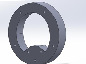
Which gives us for a male ring + female ring + hose clamp assembly.

Which gives us for a male ring + female ring + hose clamp assembly.

So we have an established technique and shape for our rings, we will now have to optimize this first version and model variations of them for the nose and for the tail. For the nose ring, a disc must be created to accommodate three other carbon tubes

A ring is also made for the tail of the aircraft with space for the support tubes of the control surfaces.
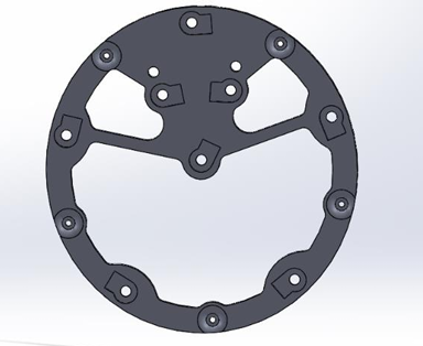
General description of a final version of a ring (in this case, the nose ring):
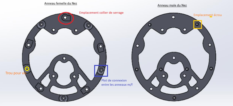
The two parts of the rings are held in place by screws and nuts through them, for optimal support, the addition of studs that will interlock and keep the rings facing each other. The clamps will therefore be perfectly included in the ring and will not be able to be disengaged.
Wings
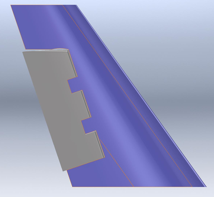
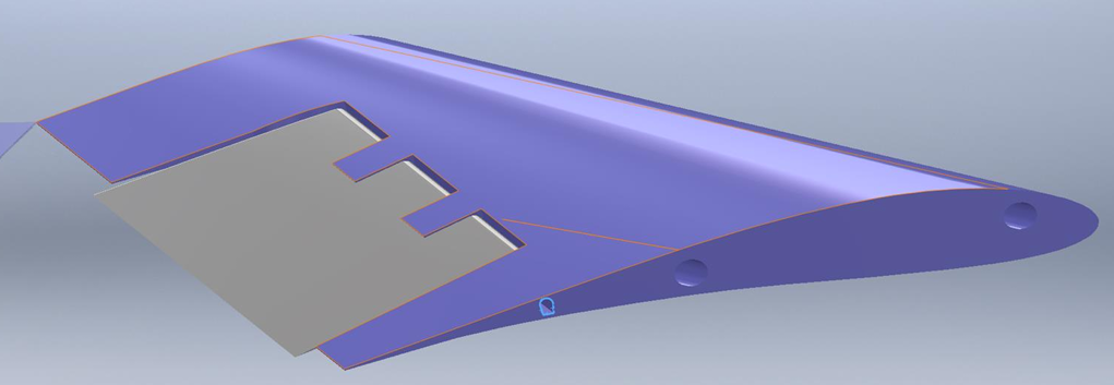
The wing is divided into 3 sections as seen the figures. The goal of this was to being able to modify separately without the need of re-fabricate the wing at each modification. Also, we were limited
by the maximum printing dimensions of 3D printers which is 30cm maximum in height.
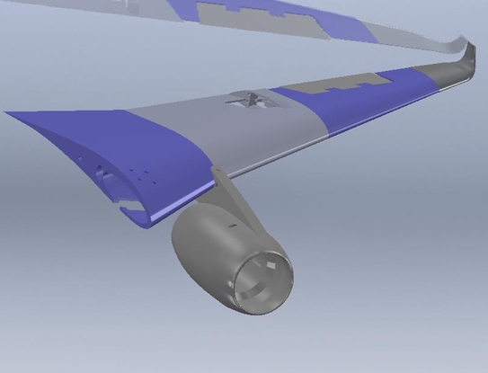
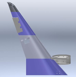
Section 1
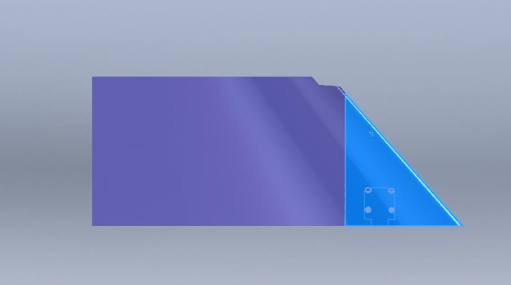
Here you can see the two pieces of the first section (separated for printing).

The first section contains the landing gear which slide here in red and the hole for the cable in green.
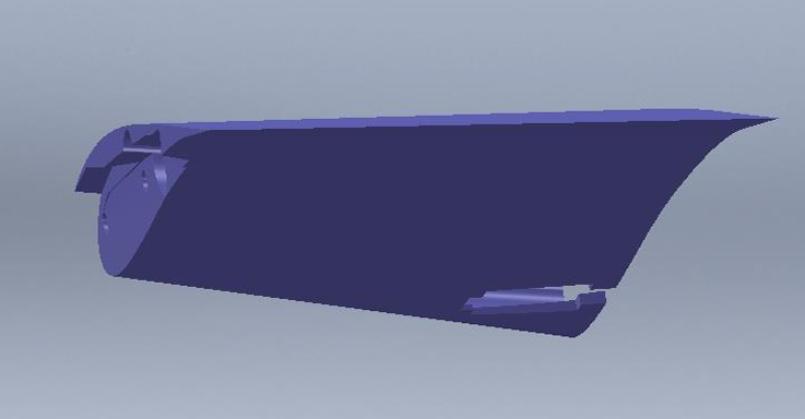
On the other end of the piece, the edge isn’t straight, it is cut so that the landing gear integrate in the first and the second section as you can see on the first picture of the win section.
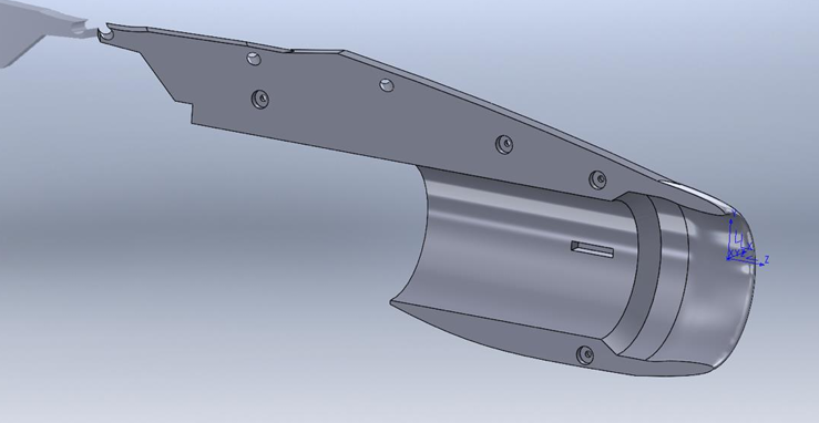
Engine Mount
The engine mount is essential for maintaining the engine on the wing. This is why careful consideration is required for the attachment of this component! Indeed, the engine mount will be secured to the 3 carbon tubes located within the wing, thereby distributing the weight of both the engine mount and the engine through these 3 rods.

Furthermore, the wing’s inclination of 10° relative to the ground had to be taken into account. Hence, an additional 10° inclination was incorporated into the attachment between the wing and the engine mount to align the engine « straight. »
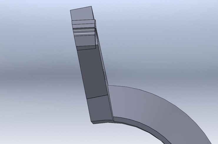
Lastly, aerodynamics plays a crucial role in aircraft design, especially concerning the engine mount, often referred to as a nacelle. It must be designed to minimize aerodynamic drag. Our mount is streamlined to reduce air resistance. That’s why we opted for this particular shape:
Section 2
Here you can see the two pieces of the second section :
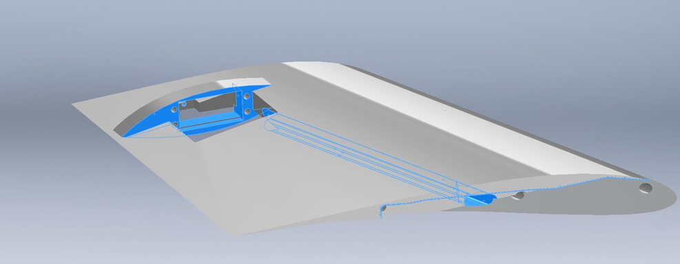
On this photo, you can see that the edge of the second section isn’t straight, the same as the first section, it is for the integration of the landing gear, you can also see the hole for the cable and where the servo will be for moving the fin (section 3)
Section 3
Tail
Rudder and Elevator

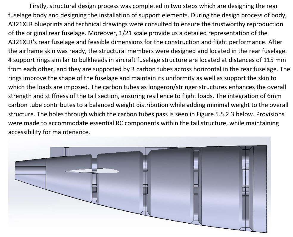
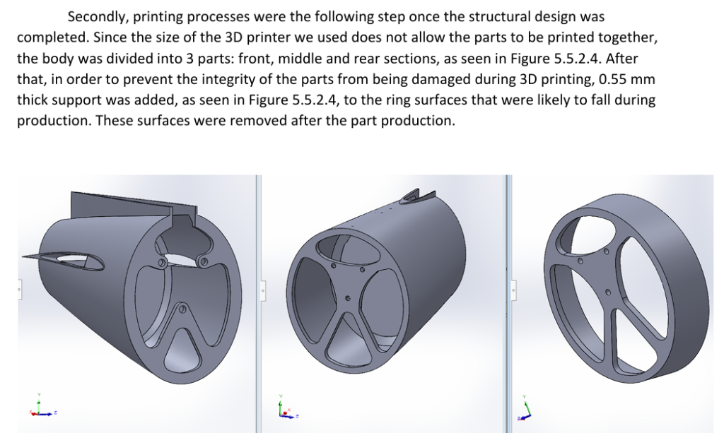
Rear Fuselage (Tail Body)

Avionics
Introduction
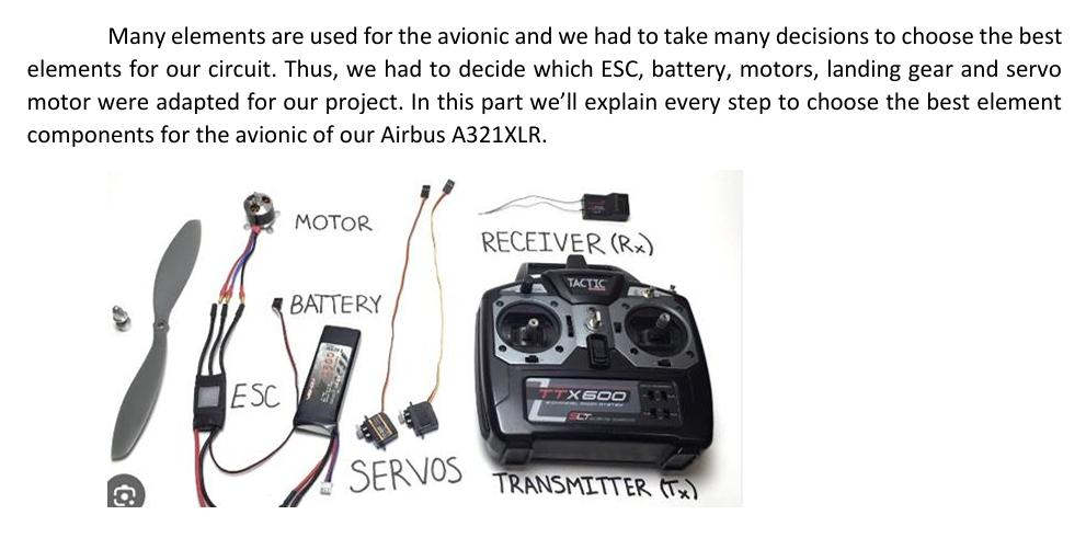
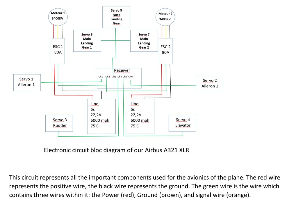
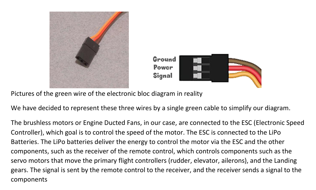
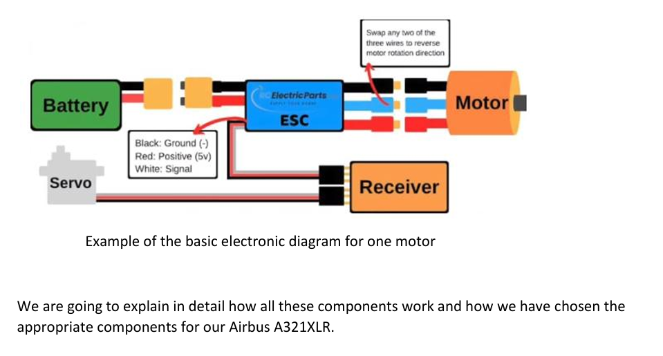
The electronic circuit of the plane
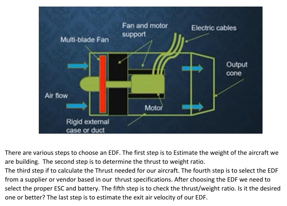
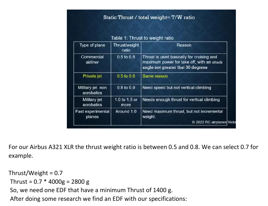
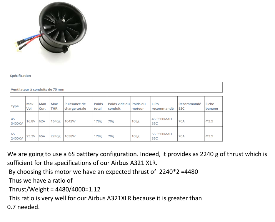
Choosing the Engine Ducted Fan (EDF)

