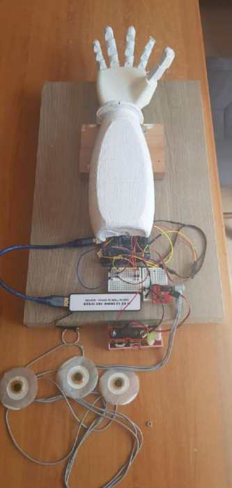
In this article, I will present the project that I carried out in my second year of preparatory class. The theme of the year was health and prevention. Therefore, I had to choose a topic related to health and engineering. I decided to design a prosthetic hand. First, I conducted a state of the art on prosthetics. Then, after using EMG electrodes, I designed a prosthetic hand.
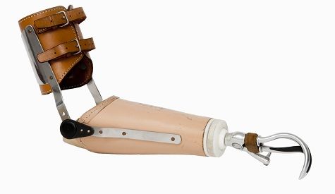
The first prostheses were made up of a simple hook. Nowadays, there are different types of bionic prostheses such as electronic prostheses that do not use nerve signals but are equipped with artificial intelligence that adapts to the person. Neuroleptic prostheses allow for precise movements but require surgery. There are also hydraulic and myoelectric prostheses. The majority of prostheses on the market use myoelectricity. I was particularly interested in myoelectric prostheses, and here are some pictures of myoelectric prostheses:
What is a myoelectric signal?
EMG stands for electromyography: the study of the electrical signals of muscles. EMG is sometimes referred to as myoelectric activity. The first research on myoelectric signals was conducted by Francesco Redi in 1666. It was in the mid-19th century that Dubois-Raymond discovered that it was possible to record the electrical activity during a voluntary muscle contraction. The first recording of this activity was made by Marey in 1890, who also introduced the term electromyography.
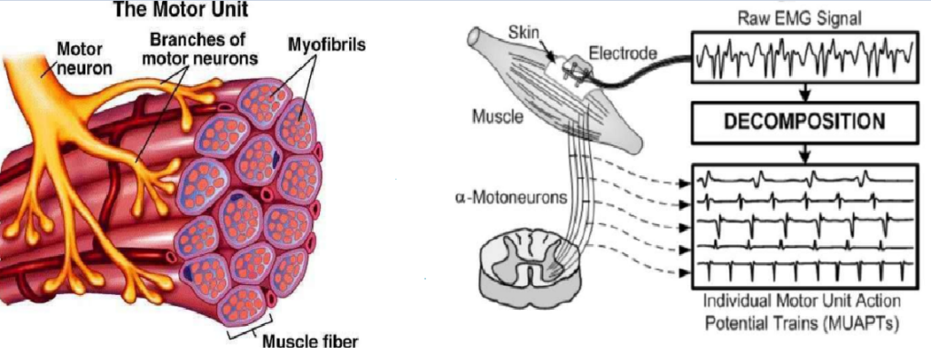
Muscle tissue conducts electrical potentials in the same way as nerves. The name given to these electrical signals is the muscle action potential. When we want to perform an action, our brain sends signals through our nervous system. Muscles are innervated in groups called motor units. This is where the nerve cell specialized in controlling movements (motor neuron) and muscle fibers meet. When the motor unit is activated, it produces a ‘motor unit action potential.’ As long as the muscle generates force, the activation of the motor unit is continuous. This produces trains of motor unit action potentials. The trains of simultaneously active motor units overlap to produce the EMG signal.
There are different types of electrodes:
Surface electrodes: These are non-invasive electrodes that are placed on the skin.
Needle electrodes: These are invasive electrodes that are inserted directly into the muscle tissue. They can record individual muscle fibers.
Concentric electrodes: These are specialized needle electrodes with a small central wire surrounded by a hollow outer tube. They are used for recording motor unit action potentials, which are the electrical signals generated by a single motor neuron and the muscle fibers it innervates.

I was interested in EMG surface electrodes
Getting familiar with the electrodes
I bought myoelectric electrodes to test them with my Arduino. Here’s the setup required to make the EMG electrodes work. The kit I bought consisted of three electrodes and an amplifier.
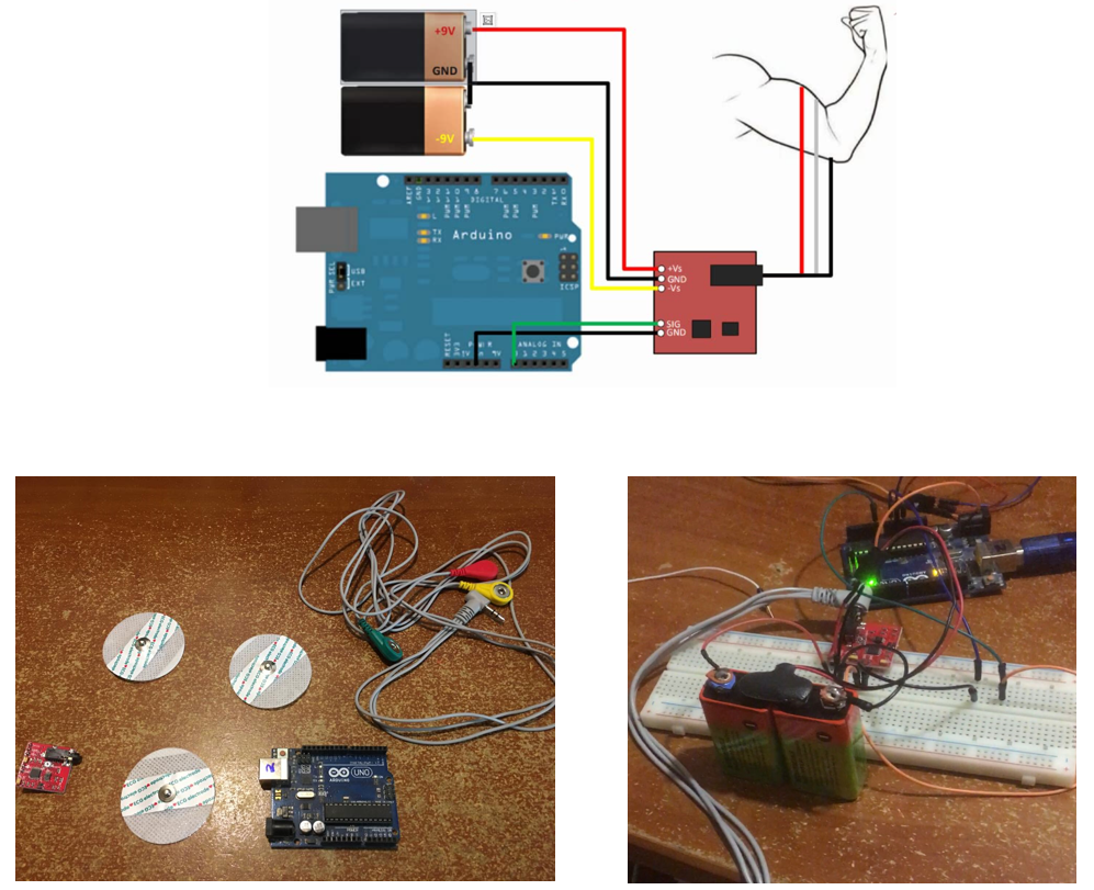
I needed to know which output pin of the amplifier corresponded to which electrode. So, I used a multimeter and set it to continuity mode. This allowed me to match the three outputs of the amplifier to the three electrodes, as you can see in the image below:
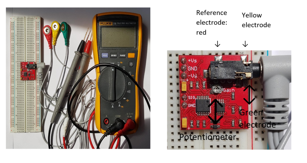
Study on electrode positioning :
I conducted a study on the positioning of electrodes in order to determine where to place each electrode. My goal is to be able to reproduce the closing of the hand with my myoelectric prosthesis. I studied the muscles involved in closing or squeezing my hand. I concluded that different muscles in the forearm come into play depending on the fingers, as you can see in this image:
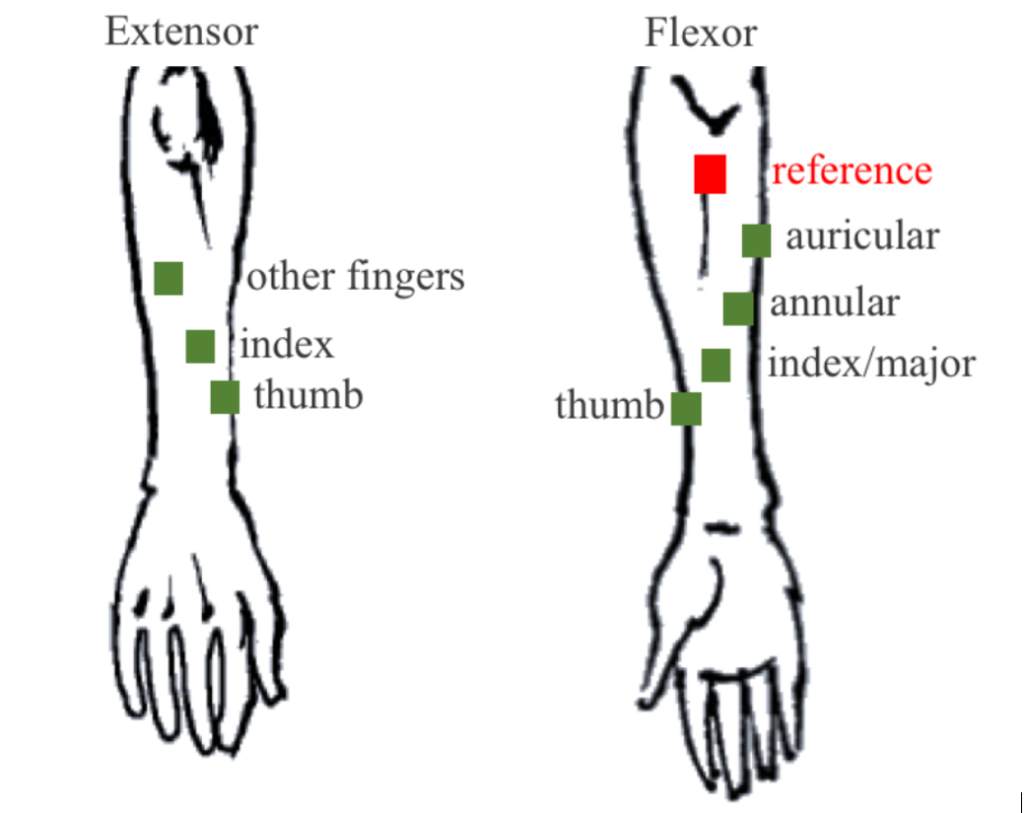
I also learned that the reference electrode should be placed in a bony area away from the two main electrodes. For the two main electrodes, the first electrode should be placed in the middle of the muscle and the second at the end of the muscle. In my case, the red electrode was the reference electrode, and the green and yellow electrodes were the two main electrodes.
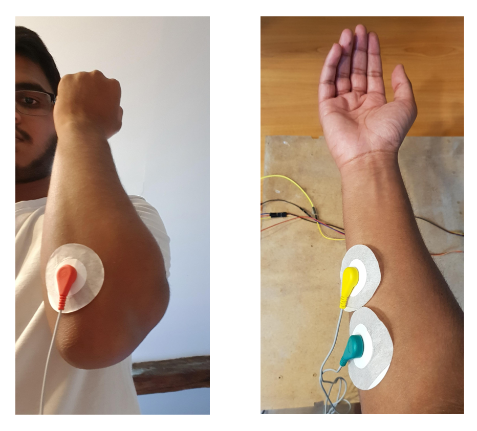
Experiments:
I conducted two experiments. Firstly, I measured the EMG signal with my arm at rest, and then secondly, I measured the EMG signal while clenching and unclenching my hand. Here are the results that I obtained:
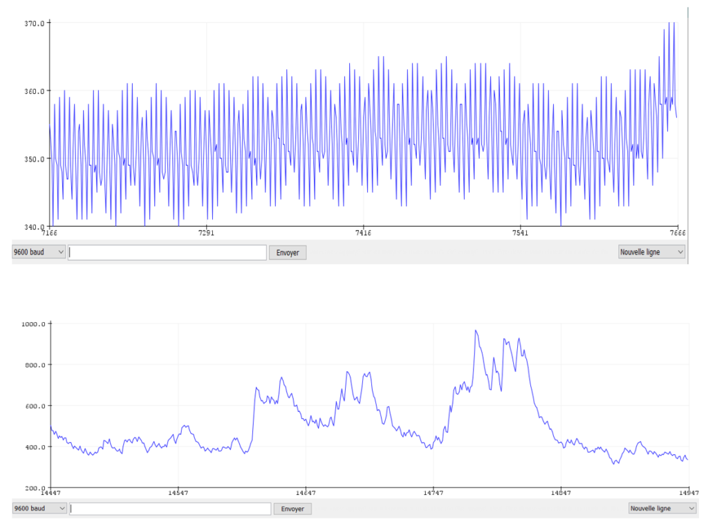
First experience (first graph) with resting arm:
We observe a zoomed-in signal that looks like a myoelectric signal. The values are less than 600 (2.9 volts) and are approximately 200-300 (0.9V-1.4V)
Second experience (second graph)while clenching and unclenching my hand:
We observe a zoomed-out signal with values ranging between 500 (2.4V) and 1000 (4.8V).
You can find down below my arduino code :
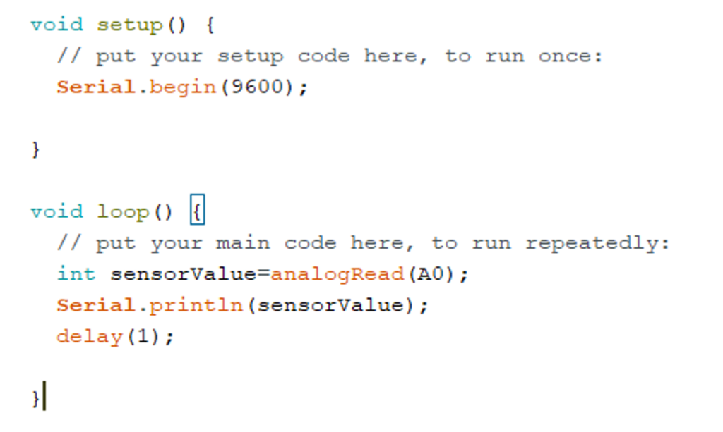
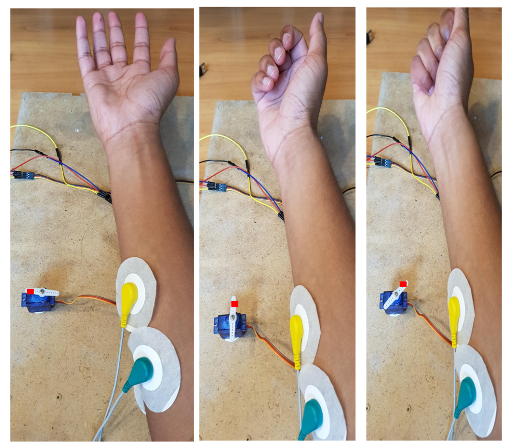
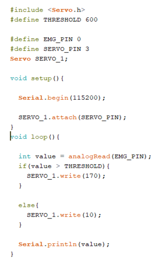
After conducting several series of measurements while clenching and unclenching my hand, I identified the values that appeared most frequently when I clenched my hand. Based on this value, I decided to create an Arduino code that can activate a servo when this threshold value is reached, simulating the closing of my hand
Here are some pictures of this experiment:
Designing the bionic arm
First, I created a specification document to model my hand prosthesis. I’ll translate what I wrote in my specification document:
In the first section, I listed the first functionality that my myoelectric prosthesis should have. The hand must be able to imitate a human hand. For this, the electrodes must be positioned at the forearm (according to my study on electrode positioning where I explained that when I close or open my hand, the muscles involved are located in the forearm). Then, the prosthesis must be able to hold an object. To achieve this, I decided to model fingers. To record the muscle signals, I use EMG sensors. The design of the prosthesis must respect the environment. For example, I decided to use my 3D printer and a recycled oil bottle. The prosthesis must be able to be powered by an independent power supply. For this, the prosthesis is powered by a battery.
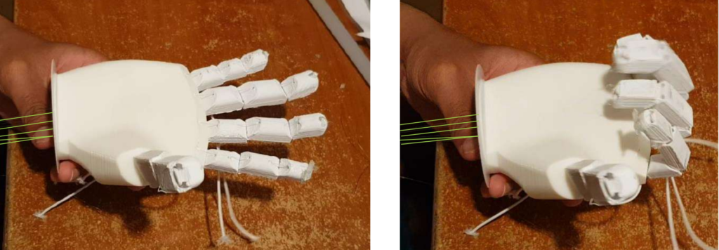
To be able to open and close my hand, I was inspired by a cardboard hand prosthesis that I had designed as a child. I had to cut the cardboard in the shape of an arm and hand. Then, I had to fold the cardboard at the finger joints and attach two cylindrical pen caps to each joint. Finally, I had to pass threads through each pen cap and tie them to the end of the fingers. When pulling on the threads, the fingers close, and when releasing the threads, the fingers open. Thus, it models the opening and closing of a hand.

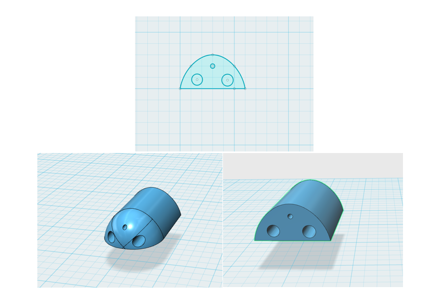
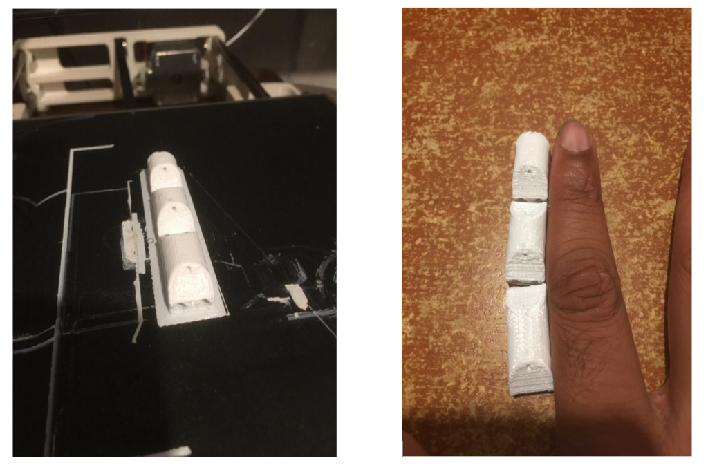
Here are some pictures of the first CAD (Computer-Aided Design) that I made for a finger model. As you can see, the two bottom holes act as ligaments, allowing the fingers to remain stable and not fall under the effect of gravity. I thread a shoelace through both holes on the underside of the fingers. The small hole on the upper part serves as tendons, where I will place the nylon thread that will enable the fingers and hand to open and close. »
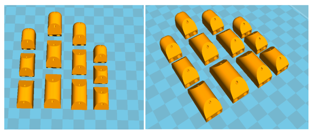
3D Printing of the Index Finger
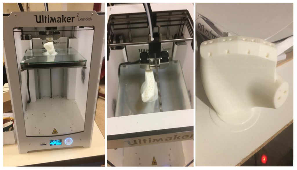
3D Printing of the Hand
Mechanism of the fingers


Here is the Arduino code I wrote to operate the servo with the EMG sensors
To operate my myoelectric prosthesis, I used a mini servo to articulate the thumb and another servo to articulate the four other fingers.

Conclusion
We can therefore see that developing a myoelectric hand prosthesis is not an easy task. Current myoelectric prostheses are expensive, making it difficult for a part of the population to obtain them. The lack of sensory feedback from patients is a recurring problem in current prostheses.
This project allowed me to learn and discover a different aspect than aeronautical engineering. I was able to develop my knowledge in programming (Arduino) and electronics, as well as in modeling. Through this project, I had the opportunity to deepen my modeling skills using computer-aided design software such as SolidWorks, Autodesk Fusion 360.